Why does spot size affect penetration depth?
Larger laser spot sizes deliver energy/fluence deeper into the dermis due to reduced scattering loss. Dermal collagen fibers scatter light (400-1200nm). Longer (red/infrared) wavelengths scatter forward, while shorter (blue/green) wavelengths scatter at wider angles, affecting penetration depth.
A small-diameter beam scatters photons outwards, decreasing fluence with depth. Larger spot sizes, with the same fluence, require more energy (photons). While scattering still occurs, a significant portion of scattered photons are redirected within the larger beam, maintaining fluence deeper than in smaller beams where photons are proportionally lost to surrounding tissue.
Think of it like cars on a motorway: a wider motorway (larger spot size) retains more cars (photons) despite exits (scattering), compared to a narrow motorway where cars easily exit. Thus, larger spot diameters, at the same fluence, penetrate deeper.
However, penetration depth doesn’t increase beyond an ~11mm spot diameter. Also, absorption by superficial chromophores (e.g., melanin in darker skin) reduces energy reaching deeper targets. The “Useful Penetration Depth” depends on wavelength, anisotropy, and sufficient fluence to achieve the desired effect (e.g., follicle destruction).
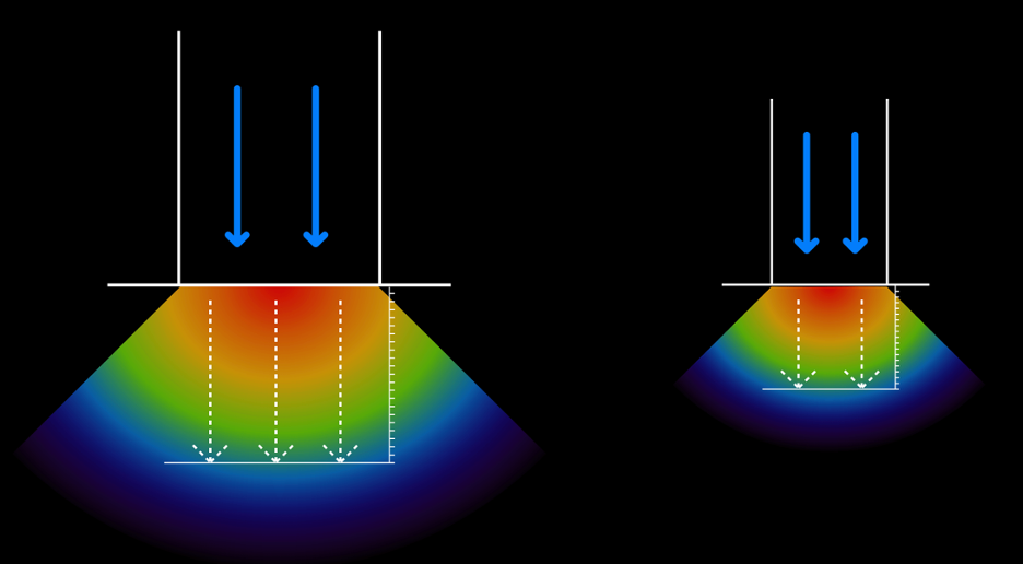
Light propagation within skin tissue is predominantly governed by scattering phenomena. The scattering characteristics are determined by the incident wavelength and the anisotropy factor (g), which describes the average cosine of the scattering angle. At a constant fluence (energy density, J/cm²), larger beam diameters contain a greater number of photons compared to smaller diameter beams.
In larger diameter beams, scattering events predominantly result in photon redistribution within the beam’s cross-sectional area. Conversely, smaller diameter beams experience a proportionally greater loss of photons from the original beam path due to lateral scattering into surrounding tissue. Consequently, larger diameter beams demonstrate superior penetration depth, delivering a higher photon flux to deeper tissue layers compared to smaller beams at equivalent fluence.
Useful Penetration Depth
The efficacy of fluence delivery at a specific depth is contingent upon achieving the desired therapeutic effect. For instance, selective photothermolysis of follicular germ cells necessitates delivering sufficient fluence to the depth of the bulge region to induce thermal damage.
This necessitates the concept of “Useful Penetration Depth,” defined as the depth at which the fluence remains sufficient to achieve the intended therapeutic outcome. This parameter is dependent not only on the wavelength and anisotropy factor but also on the applied fluence. While a relatively low fluence delivered via a large spot diameter may result in some photon flux reaching the bulge region, it may be insufficient to induce the required thermal damage. A higher fluence is therefore necessary to achieve the desired therapeutic endpoint.
The process of making a laser rod is a highly specialized and intricate one, requiring extreme precision and control at every stage. Laser rods are the “active medium” or “gain medium” in solid-state lasers, where the light amplification occurs.
Here’s a general overview of the process:
1. Material Selection and Preparation (The Host Crystal):
- Host Material: The foundation of a laser rod is a crystalline or glass “host” material. Common choices include:
- Yttrium Aluminum Garnet (YAG): Highly popular due to its excellent optical and mechanical properties, high thermal conductivity, and ability to be doped with various ions. (e.g., Nd:YAG)
- Yttrium Lithium Fluoride (YLF)
- Yttrium Orthovanadate (YVO4)
- Sapphire (Al2O3): Used for Ti:Sapphire lasers.
- Various types of glasses: Less common for high-power applications due to lower thermal conductivity, but can be used for very large rods or specific pulsed applications.
- Dopant (Laser-Active Ions): The host material is then “doped” with specific rare-earth ions or transition metal ions that absorb energy and emit light through stimulated emission. Common dopants include:
- Neodymium (Nd3+): For Nd:YAG, Nd:YLF, Nd:YVO4, producing near-infrared light.
- Ytterbium (Yb3+): For Yb:YAG, often used in high-power, high-efficiency lasers.
- Erbium (Er3+): For Er:YAG, used in medical applications (e.g., 2.94 µm wavelength).
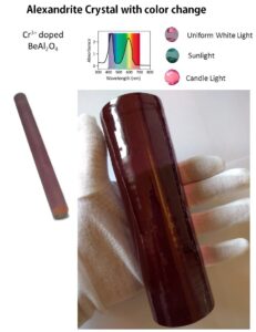
- Chromium (Cr3+ or Cr4+): Used in ruby lasers (Cr:Al2O3) or as a Q-switch material.
- Holmium (Ho3+) and Thulium (Tm3+): Often co-doped for specific infrared wavelengths (e.g., Ho:Cr:Tm:YAG for 2.1 µm).
- Raw Material Purity: Extreme purity of the raw materials is crucial to prevent defects and inclusions that could scatter light or damage the rod during laser operation.
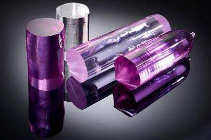
2. Crystal Growth (Creating the “Boule”):
- This is the most critical and complex step. The doped host material is melted, and a single crystal is grown from this melt. The most common method is the Czochralski (Cz) method:
- A small seed crystal, precisely oriented, is dipped into the molten material.
- The seed is slowly pulled upwards and rotated, causing the molten material to solidify and grow onto the seed, forming a large, cylindrical single crystal ingot, known as a “boule.”
- This process can take weeks or even months for large boules, and precise control of temperature, pulling rate, and rotation speed is essential to ensure crystal quality, homogeneity of doping, and minimal defects.
- Other methods like Floating Zone or Bridgman might be used for specific materials.
3. Annealing:
- After growth, the boule often undergoes an annealing process. This involves heating the crystal to a high temperature and then slowly cooling it down. Annealing relieves internal stresses that developed during the rapid cooling of crystal growth, which helps prevent cracking and improves the optical uniformity of the crystal.
4. Shaping and Cutting:
- The large crystal boule is then carefully inspected for any imperfections.
- Using diamond-impregnated saws, the boule is precisely cut into rough blanks or pre-forms of the desired rod dimensions (e.g., cylindrical, rectangular slab). The orientation of the crystal lattice is critical for optimal laser performance and must be maintained during cutting.
5. Grinding and Lapping:
- The cut blanks are then ground to refine their shape and achieve preliminary dimensions.
- Lapping follows, using progressively finer abrasive slurries, to create smoother, more precise surfaces. This removes subsurface damage caused by grinding.
6. Polishing:
- This is a highly meticulous step. The ends of the laser rod (the “optical faces”) and sometimes the barrel (cylindrical side) are polished to an extremely high optical quality. This involves using very fine polishing compounds and specialized machinery to achieve:
- Exceptional flatness: Often measured in fractions of a wavelength of light (e.g., λ/10 or better).
- High parallelism: The end faces must be perfectly parallel to each other (or precisely angled for specific designs like Brewster-angled ends).
- Minimal surface roughness: Measured in angstroms or nanometers, to reduce scattering losses and increase the laser-induced damage threshold (LIDT).
- Subsurface damage from previous steps must be completely removed.
7. Cleaning:
- After polishing, the rods undergo rigorous cleaning processes, often involving ultrasonic baths with various solutions, to remove all traces of polishing compounds, oils, and contaminants. Any residual debris can severely impact coating quality and laser performance.
8. Optical Coating:
- The highly polished optical faces of the rod are then coated with specialized thin films. These coatings are crucial for the laser’s operation:
- Anti-Reflection (AR) Coatings: Applied to minimize reflections at the surfaces, allowing maximum pump light to enter the rod and maximum laser light to exit.
- High-Reflection (HR) Coatings: In some designs, one end of the rod might have a highly reflective coating to act as one of the laser cavity mirrors.
- Partial Reflective (Output Coupler) Coatings: The other end might have a coating that allows a specific percentage of light to transmit, forming the laser output.
- Coatings are typically applied using vacuum deposition techniques (e.g., ion-assisted deposition, e-beam evaporation) to achieve precise thickness and refractive index for the desired wavelengths.
9. Metrology and Quality Control:
- Throughout the entire process, and especially at the final stages, extensive metrology and quality control checks are performed. This includes:
- Dimensional measurements (length, diameter, parallelism, perpendicularity).
- Surface quality inspection (scratch-dig specifications).
- Interferometry to check surface flatness.
- Spectrophotometry to verify coating performance.
- Homogeneity testing of the dopant.
- Laser-Induced Damage Threshold (LIDT) testing: Crucial for high-power lasers, where the rod is tested with actual laser pulses to determine the maximum energy density it can withstand without damage.
10. Packaging:
- Finally, the finished laser rods are carefully cleaned once more and packaged in protective, often dust-free and anti-static, containers to prevent contamination or damage during shipping.
The entire process demands exceptional expertise in materials science, crystal growth, optical fabrication, and thin-film coating to produce laser rods that meet the stringent performance requirements of modern laser systems.